Blog post you’re reading right now is privately hosted on Raspberry PI 4 Kubernetes cluster with its data coming from NFS share and MariaDB on a Synology NAS. Purpose of this post is to serve as an ultimate guide on how to build a (prod ready) RPI k8s cluster and deploy WordPress CMS to it. Also don’t worry if you don’t have a Synology device, as I’ll explain how to use alternative solutions to achieve the same result in terms of storage and accessibility.
This is an extension to wp-k8s (WordPress on Kubernetes) project, and below is a simplified diagram of my on-prem (home) infrastructure which only focuses on a single domain and service (WordPress).

But, why?
Recently I’ve decided to leave world of VM’s by performing migration from AWS Lightsail to GKE as described in: wp-k8s: WordPress on Kubernetes project (GKE, cloud SQL, NFS, cluster autoscaling, HPA, VPA, Ingress, Let’s Encrypt). However, it didn’t take me long to realize costs would be much higher then I initially estimated and naturally much higher then I used to pay in VM world.
Considering I have a Synology DS920+ with 32 TB of storage, along with another Synology DS415 NAS used for backup and replication in offsite location (different country). Initial idea was to use this NAS for storage (NFS & MySQL/MariaDB) and only use GKE for the workloads (K8S cluster/nodes & Loadbalancer). But considering most of my costs were coming exactly from those two components, I thought why not just not build a Raspberry PI (RPI) K8s cluster?
I tried doing this before, on 2nd or 3rd generation of RPI’s, but experience was so sub-optimal that I abandoned the project and thought of never even coming near a RPI. But by taking a quick look at the landscape, this time around things have changed a lot (for the better). There’s a RPI 4 which seems more then capable of performing one such task, and there’s a plethora of available (production ready) lightweight Kubernetes distributions.
Private cloud acceptance criteria
Acceptance criteria for this project was it would have to be production ready in terms of reliability and security, and most importantly: minimum to no ops related tasks. As big appeal of public cloud is that Google/Amazon/Microsoft engineers are the one maintaining underlying infrastructure your services are running on. While having it privately hosted means you have to take care of it which can be a very daunting task, hence this aspect had to be eliminated.
Step 1: Choosing the software
In this category, I wanted things to be as lightweight as possible without having to make any compromises. I also wanted to have Kubernetes distribution that would be as vanilla flavor of Kubernetes as possible.
In this category it came down to either using k3s or microk8s. I opted for microk8s, as it meant running an Ubuntu server which has a nifty feature called automated unattended updates. Furthermore, microk8s is installed as a snap package (read container) which meant it would be running Kubernetes natively without any VM’s while sharing some of the same resources (i.e kernel) with the host OS itself. Meaning it would also have a minimal footprint.
Step 2: Choosing the hardware
In this section I’ll go through hardware choices this setup consists of.
* 3 x Raspberry Pi 4 model B with 4GB of RAM – 3 nodes will provide high availability for the cluster with option of 1 node (RPI) dying and cluster still working just fine. 4GB of RAM will work just fine with wp-k8s and few other things running on the cluster. I purposely chose 4GB instead of 8GB as it keeps me optimizing my workloads and container images instead of dumping just about anything. If I have intensive workloads, I’ll add my old X1 Carbon as a node to the cluster and with help of affinity nodes/pods put intensive workloads on it.
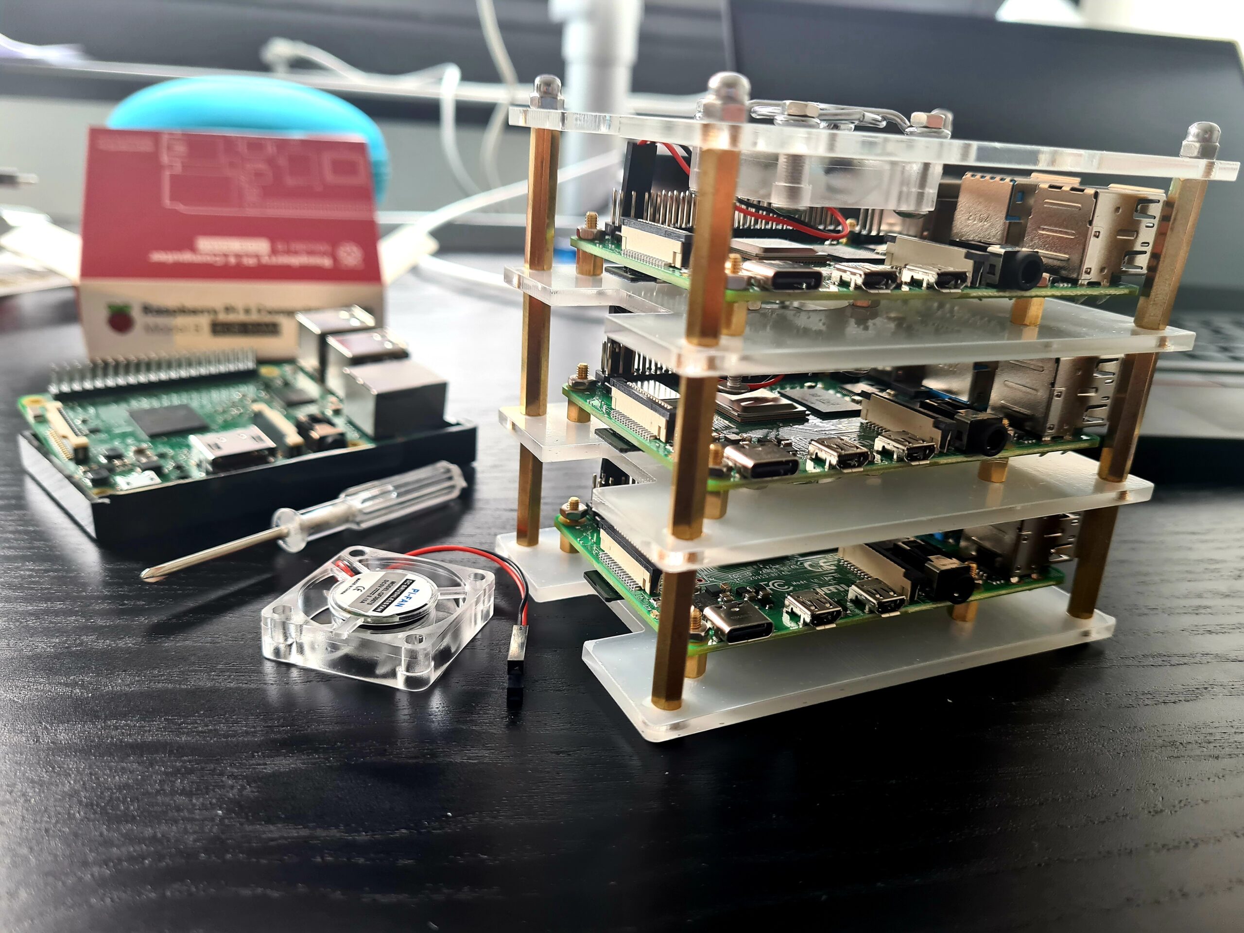
* 3 x SanDisk Max Endurance microSD (32GB) – Since k8s cluster will make a lot of read/writes regular sd card would be trashed in no time, this card claims to last for 13 years. Alternative to the sd card was using NFS as my file-system, or using some of the old USB drivers and USB external hard drives (SSD). This sd card seemed as cheapest, most reliable and sensible option.
* 3 x USB C phone chargers – while I originally bought 3 x original Raspberry chargers, being disappointed how poorly they’ve been designed (they took a lot of unnecessary space around them) that I returned them. Another option I’ve considered is an USB hub, but decided not to get it as if it died, all 3 of my RPI’s would be shut down.

* Synology DS920+ NAS (optional) – is used for NFS storage, as a MariaDB/MySQL database, Let’s Encrypt certificate issuer and reverse proxy. Depending on your needs you might be interested in 2 bay disk Synology devices which are much cheaper. if you don’t want to use Synology at all, if you’re using wp-k8s, you can use my nfs-server-k8s (as part of nfs.yaml) to deploy NFS server (i.e USB external hard drive attached to your RPI which can server as a NFS share) and create MySQL cluster on RPI K8S cluster as part of mysql-cluster.yaml.
* Synology DS415 NAS (optional) – used for backup and replication in off site location (another country). In case of theft, fire or other elementary disasters, this device will have copy of my data.
* APC Back-UPS 850VA (optional) – used to provide power to key components (RPI’s, Synology, Router) in case of power outage. Furthermore, once UPS is out of power it’ll shut down necessary (connected) devices gracefully to prevent data loss, example:

* Fast or gigabyte internet connection (optional)
Step 3: Installing and configuring Ubuntu server on RPI 4’s nodes
This step will need to be done on all RPI nodes that will form the k8s cluster. While this seems as a lengthy process, steps described below will only need to be done once.
Please note: after image has been written to SD card, most of steps described in Step 3 & 4 section can be done automatically using: rpi-microk8s-bootstrap: Automate RPI device conversion into Kubernetes cluster nodes with Terraform project.
* Step 3.1: Write Ubuntu server >= 20.04.x arm64 image to RPI’s – since I’m using Ubuntu I did this using Raspberry PI Imager.

Since in this setup all nodes were setup in headless manner, using following options before writing the image to sdcard will make things much easier.

As you’ll enable SSH access, you’ll know username/password combination to use, and you’ll be able to find IP on which your RPI node will be on with:
ping rpi-a.local or using nmap: nmap -sn 192.168.1.1/24
* Step 3.2: Passwordess SSH (optional) – once Ubuntu is installed and you can SSH to your RPI with username and password “ubuntu” (after first login you’ll be forced to change this password). However instead of having to type in the password every time you SSH to one of your RPI nodes, you can enable SSH login based on your SSH key. This can be done by getting your SSH public key cat ~/.ssh/id_rsa.puband copying its contents to.ssh/authorized_keyson RPI node.
* Step 3.3 – change PRI hostname – this will help greatly so you know what operations you’re doing on each RPI. The way I ordered them is by “rpi-a/b/c”, changing hostname can be done by running, i.e:sudo hostname rpi-aand adding “rpi-a/b/c” to etc/hostname
* Step 3.4 – Get latest updates and configure automated unattended updates:
To install latest updates simply run: sudo apt update && sudo apt upgrade -y
While Ubuntu server comes with unattended security updates enabled by default, you might want to further configure them to your liking.
* Step 3.5: Install packages necessary for NFS mount – if you’re planning to use NFS for storage by either using Synology or nfs-server-k8s and this step isn’t done, NFS mount will fail, hence make sure to run:sudo apt install nfs-common -y
* Step 3.6: Configure boot configuration for use ofcgroupmemory
Without configuring this, Kubernetes setting will never get to “Ready” state!
Edit/boot/firmware/cmdline.txtfile and add following to the beginning of the file:cgroup_enable=cpuset cgroup_enable=memory cgroup_memory=1
followed by RPI reboot :sudo reboot
* Step 3.7: Configuring static IP on Ubuntu server RPI nodes. We must know where each RPI node will be located on our network, for this we need them to be behind static IP’s.
* Step 3.8: Disable cloud-init network capabilities for changes to persists across reboots. Edit:/etc/cloud/cloud.cfg.d/99-disable-network-config.cfg
file to contain:network: {config: disabled}
* Step 3.9: Check contents of existing network config: /etc/netplan/50-cloud-init.yaml
Which should be as follows:
# This file is generated from information provided by the datasource.  Changes
# to it will not persist across an instance reboot.  To disable cloud-init's
# network configuration capabilities, write a file
# /etc/cloud/cloud.cfg.d/99-disable-network-config.cfg with the following:
# network: {config: disabled}
network:
    ethernets:
        eth0:
            dhcp4: true
            optional: true
    version: 2
* Step 3.10: Comment existing contents and add static configuration. Please note, that your device might/will be different then mine “eth0”, and make sure to change last number (100) ofaddresses: [192.168.1.100/24]accordingly for each node. You also might be interested in using different nameservers address, i.e: 8.8.8.8 for Google DNS, if you’re not happy with your ISP.
# This file is generated from information provided by the datasource.  Changes
# to it will not persist across an instance reboot.  To disable cloud-init's
# network configuration capabilities, write a file
# /etc/cloud/cloud.cfg.d/99-disable-network-config.cfg with the following:
# network: {config: disabled}
#network:
#    ethernets:
#        eth0:
#            dhcp4: true
#            optional: true
#    version: 2
network:
  ethernets:
    eth0:
      addresses: [192.168.1.100/24]
      gateway4: 192.168.1.1
      nameservers:
        addresses: [192.168.1.1]
  version: 2
Apply changes by running:sudo netplan apply
* Step 3.11: Add IP of each RPI node to/etc/hosts– without this RPI nodes won’t properly know about each other’s location, and you will face :Error from server: error dialing backend: dial tcp: lookup node-c: Temporary failure in name resolution type of errors when trying to run kubectl on different RPI nodes. This can be fixed by adding following to each RPI node’s/etc/hostsfile:
192.168.1.100 rpi-a
192.168.1.101 rpi-b
192.168.1.102 rpi-c
* Step 3.12: Add SSH aliases (optional) – this will allow you to quickly SSH to target RPI node’s from localhost, on Linux add to following to your~/.bashrc
# rpi k8s cluster
alias rpi-a="ssh [email protected]"
alias rpi-b="ssh [email protected]"
alias rpi-c="ssh [email protected]"
After which you can simply run:rpi-ain your terminal after which you’ll SSH to your RPI node.
Step 4: Installing and configuring MicroK8s
At this point make sure you’ve cloned contents of wp-k8s repository to your localhost.
Please note: most of steps described in this and previous section can be done automatically using: rpi-microk8s-bootstrap: Automate RPI device conversion into Kubernetes cluster nodes with Terraform project.
* Step 4.1: Install MicroK8s –sudo snap install microk8s --classic or if you want install particular version of microk8s: sudo snap install microk8s --channel=1.24/stable --classic
Also make sure to install “linux-modules-extra-raspi” package in order to avoid calico container getting stuck in restart loop: sudo apt instal linux-modules-extra-raspi
* Step 4:2: Eliminate need to run “sudo microk8s” by adding ubuntu user to microk8s group:
sudo usermod -a -G microk8s $USER
sudo chown -f -R $USER ~/.kube
su - $USER # or open new shell session
Please note, after this point following steps only need to be done on 1 RPI node, and you can skip to Step 4.9: Enable High Availability k8s cluster by adding rest of RPI nodes.
* Step 4.3: Enable plugins needed for wp-k8s deployment: microk8s enable dns dashboard storage ingress
* Step 4.4: Check cluster status:microk8s status
* Step 4.5: See addons deployment progress:watch microk8s kubectl get all -A
* Step 4.6: Configure access to microk8s cluster by configuring kubeconfig – microk8s kubectl config view --raw
Add output to~/.kube/configfile on your localhost and make sure to change: server: https://127.0.0.1:16443line to server: https://192.168.1.100:16443
* Step 4.7: Enable and configure MetalLB – I’ve configured MetalLB to spin off LoadBalancers in 192.168.1.110-192.168.1.120 IP range: microk8s enable ingress metallb:192.168.1.110-192.168.1.120
UpdateloadBalancerIP: redactedfield of metallb.yaml to: loadBalancerIP: 192.168.1.110if same IP range was used.
* Step 4.8: Create a service to load balance MicroK8s Ingress in order to support HA clustering: kubectl apply -f metallb.yaml
* Step 4.9: Enable High Availability k8s cluster by adding rest of RPI nodes: microk8s add-nodeand follow the instructions. Same command needs to be run for every new node that will be added to the cluster.
* Step 4.10: Verify HA – running microk8s statusshould now say “high-availability: yes”.
* Step 4.11: Runkubectlon your cluster outside of home network (optional) – change server: https://192.168.1.100:16443as part of ~/.kube/configto domain name you mapped to your Synology instance on port 16443. Refer to Secure (HTTPS) public access to Synology NAS using Let’s Encrypt (free) SSL/TLS certificate blog post for more information. Other option is to enable SSH on Synology (described in Step 6.2), once you’re in local network, SSH to one of RPI nodes and runmicrok8s kubectl
Step 5: Configure NFS on Synology (optional)
Please note! Instead of using NFS server, alternatively WP-Stateless WordPress plugin can be used, where media will be served from Google Cloud Storage bucket instead. See wp-k8s Github ReadMe for more details!
Since WordPress is not a stateless app, I use NFS to store my WordPress media data, as it provides me withReadWriteManyaccess mode and can scale WordPress deployment to numerous pods without any issues. More about this in “Problem 3.1” section of wp-k8s of GKE blogpost. If you don’t have a Synology device, you can use my nfs-server-k8s which can be used to create NFS server on a regular disk/PV.
* Step 5.1: Enable NFS – in Synology “Control Panel > File Services” go to “NFS” tab and make sure “Enable NFS Service” checkbox is checked, along with selecting NFSv4 as Maximum NFS protocol version.

Under “Advanced Settings” make sure to “Apply default UNIX permissions” checkbox is checked.

* Step 5.2: Create shared volume for NFS share – in “Control Panel > Shared Folders” click on “Create” button and select “Create Shared Folder”. Make sure “Enable Recycle Bin” checkbox is unchecked.

* Step 5.3: Configure NFS settings for newly created directory – by right clicking on it and selecting “Edit” and selecting “NFS Permissions” tab, followed by clicking on “Edit” button and make following changes:

Take note of “mount path” which will be needed later on after which NFS is ready to be used.
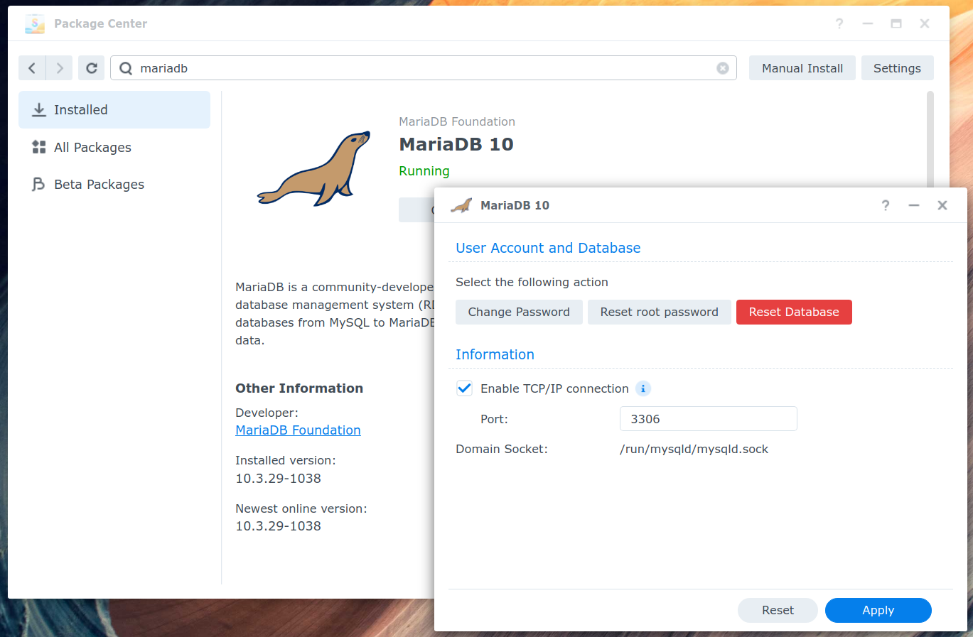
Step 6: Install and configure MariaDB database on Synology (optional)
In case you don’t own a Synology device, MySQL cluster can be setup by following wp-k8s: Step 1: Create MySQL Cluster. Make sure all usernames and passwords from this steps have been saved securely, as they’ll be needed in next step.
* Step 6.1: Install “MariaDB” package from “Package Center” and make sure it’s running.
* Step 6.2: Enable SSH on Synology so MySQL database can be created and configured. SSH access will also be necessary for use later on. For security reasons I suggest to change default port (22) to something more obscure (if Synology is accessed externally).

* Step 6.3: SSH to Synology and login to MariaDB as root user
SSH to Synology ssh -p 21092 $your_username@$synology_IP followed by: mysql -u root -p
* Step 6.4: Create WordPress databaseCREATE DATABASE wpdb;
* Step 6.5: Create “wp-db-user” user (change $PSW with password you want to use):CREATE USER 'wp-db-user'@'%' IDENTIFIED BY '$PSW';
* Step 6.6: Grant all privileges towp-db-useruser onwpdbdatabase so it can be accessible from any IP: GRANT ALL PRIVILEGES ON *.* TO 'wp-db-user'@'%' IDENTIFIED BY '$PWD' WITH GRANT OPTION;
* Step 6.7: Verify permissions granted to wp-db-userSHOW GRANTS FOR 'wp-db-user';
* Step 6.8: Apply changes:FLUSH PRIVILEGES;
After this has been done, MySQL database is ready to be connected to the WordPress instance.
Step 7: Install and configure WordPress
* Step 7.1 Fill out kustomization file:
Replaceredactedfield under:
mysql-root-passsecret name with root password created during “Step 6“
wp-db-hostsecret name with private IP ofwp-db-hostMariaDB instance (Synology IP/MySQL cluster).
wp-db-usersecret name withwp-db-usercreated during “Step 6.5“
mysql-db-passsecret name with whatever you had specified as “$PWD” when creatingwp-db-useras part of “Step 6.5“
wp-db-namesecret name withwpdbvalue for WordPress database name created during “Step 6.4“
metallb.yaml file:
loadBalancerIPshould’ve already been filled out as part of “Step 4.7“
nfs-synology.yaml file:
server– Specify IP of Synology server which was configured as NFS server in “Step 5“
path – Specify “mount path” from “Step 5,3“
wordpress-deployment.yaml file:
Uncomment #loadBalancerIP: redactedline in Service section and replace “redacted” with IP you want WordPress to be running on, i.e: 192.168.1.111
* Step 7.2: Install Vertical Pod Autoscaler (VPA) – for vpa.yaml to work VPA needs to be installed, which is as simple as running:
git clone https://github.com/kubernetes/autoscaler.git
cd autoscaler/vertical-pod-autoscaler/
./hack/vpa-up.sh
* Step 7.3: Deploy MetalLB LoadBalancer, NFS Synology mount, WordPress, VPA, HPA by making sure only following lines are enabled/uncommented as part of kustomization.yaml
Followed by running:kubectl apply -k ./
This step will create necessary secrets as part of “kustomization.yaml” file and deploy:
- metallb.yaml – explained as part of “Step 4.8“
- mysql-cluster.yaml (only if you’re not using Synology MariaDB database and want to create MySQL cluster as part of k8s cluster)
- nfs-synology.yaml – Explained as part of “Step 5: Configure NFS on Synology (optional)”
- wordpress-deployment.yaml – will create WordPress deployment using (official WordPress docker image) and its service. It will pick up secrets & variables set as part of “kustomization.yaml” file. Deployment will utilize our previously created NFS PVC. As part of a ConfigMap, various changes which to allow upload of size up 64MB. Which will fix problems of not being able to upload large files due to their file size or image dimension.
- vpa.yaml – will create VPA whose function has been described in “wp-k8s (WordPress on Kuberenetes) project” section.
- hpa.yaml – – will create HPA whose function has been described in “wp-k8s (WordPress on Kuberenetes) project” section.
Step 8: Let’s Encrypt and reverse proxy
As part of this step, we will point our domain’s DNS records to our Synology NAS, which will then perform a reverse proxy to WordPress service LB created by MetalLB.
For those who do not own a Synology device will want to use an inlets-operator, to use it in this setup, you will need to uncomment “ingress.yaml” line of “kustomization.yaml” which will create an Ingress whose functionality has been describe as part of “Step 5” of wp-k8s on GKE blog post.
* Step 8.1: Get WordPress LB IP which will be used in “Step 8.2/3“.

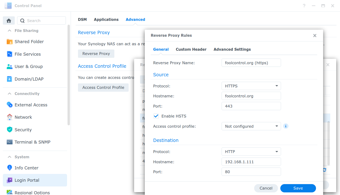
* Step 8.2: Create HTTP reverse proxy rules for your domain – by going to Control Panel > Login Portal > Advanced > Reverse Proxy > Create with following settings.

* Step 8.3: Create HTTPS reverse proxy rules for your domain – by going to Control Panel > Login Portal > Advanced > Reverse Proxy > Create with following settings:
* Step 8.4: Update DNS for your domain with IP of your Synology NAS
Step 8.5: Request Let’s Encrypt certificate for your domain name – Control Panel > Security > Certificate > Add and following on screen instructions. After certificate has been obtained, go back to “Certificate” tab, select your domain name and click on settings and make sure correct certificate is selected for your domain name.

After which your domain name will be available behind a Let’s Encrypt certificate.

Happy hacking & if you found this useful, consider becoming my GitHub sponsor!
Comments